 EN
EN


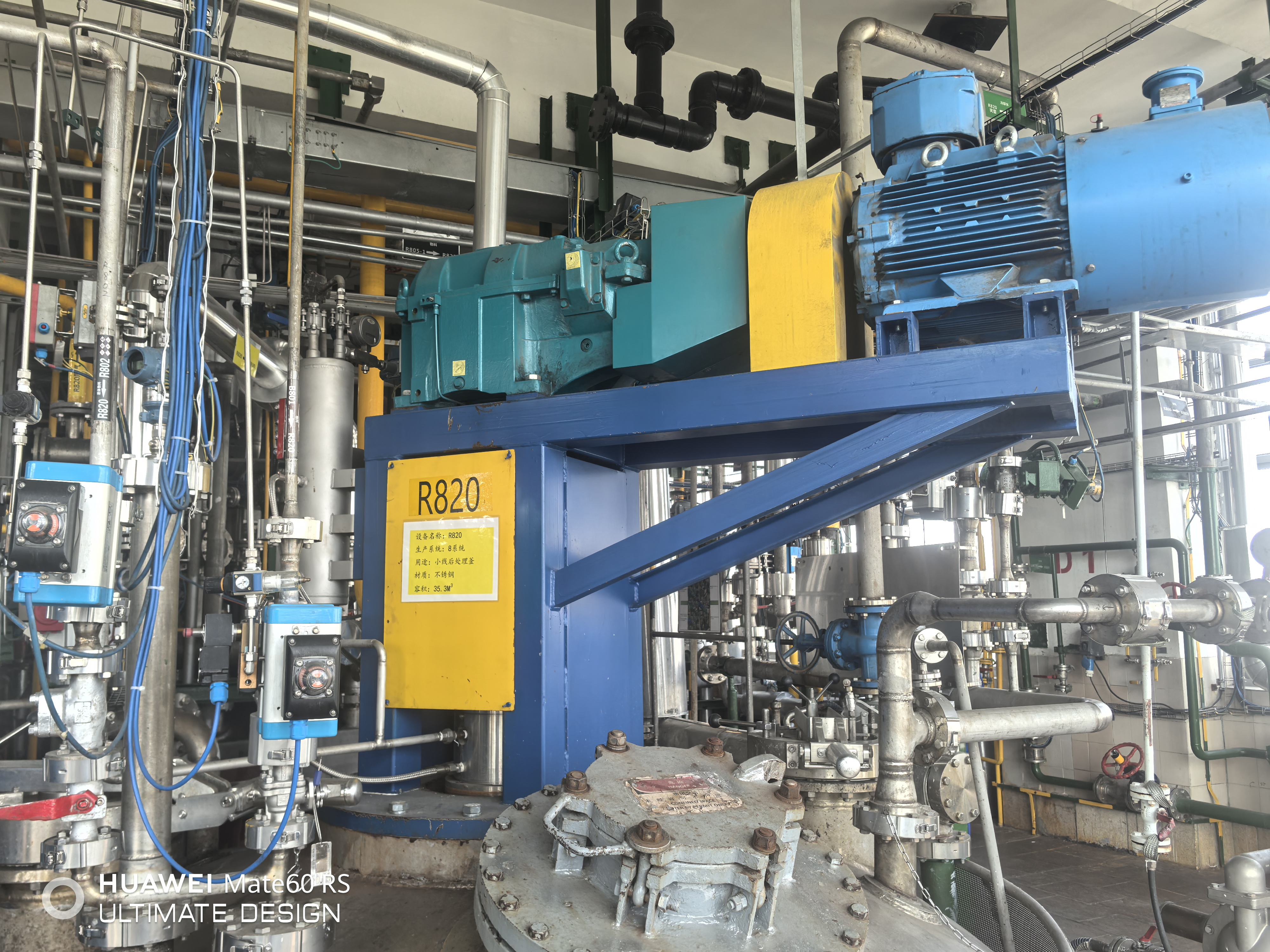
A mechanical seal is a precision-engineered sealing device designed to prevent fluid leakage between rotating and stationary components in industrial equipment such as pumps, mixers, compressors, and agitators. Unlike traditional packing methods that allow controlled leakage, a mechanical seal creates a dynamic barrier that maintains process integrity while accommodating shaft rotation. These sealing solutions are critical in industries ranging from chemical processing and petrochemical refining to water treatment and pharmaceutical manufacturing, where even minor leakage can result in product contamination, environmental hazards, or significant operational costs. Understanding what a mechanical seal is and how it functions enables maintenance teams, design engineers, and procurement professionals to make informed decisions that enhance equipment reliability and process safety.
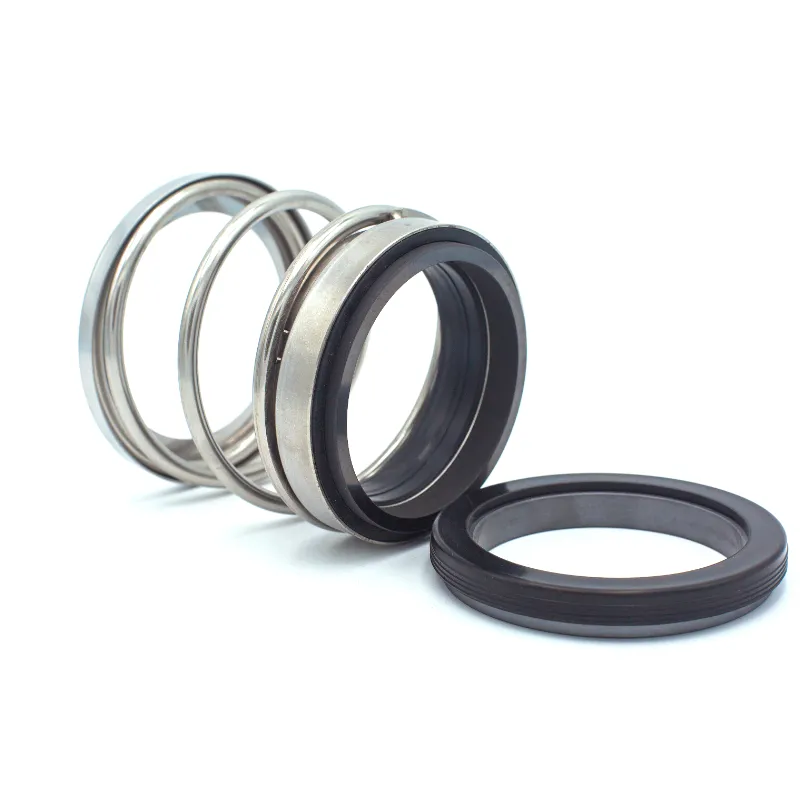
The working principle of a mechanical seal involves maintaining continuous contact between two highly polished faces—one rotating with the shaft and one stationary against the equipment housing—while a thin lubricating film separates them. This arrangement creates a seal that prevents process fluid from escaping while managing friction, heat, and wear through precise material selection and geometrical design. The effectiveness of this sealing mechanism depends on multiple interdependent factors including face material compatibility, spring loading force, hydraulic balance, and proper lubrication. By exploring the structural components, operating principles, material considerations, and application requirements of mechanical seals, this article provides comprehensive insight into why these devices have become the standard sealing solution across industrial rotating equipment worldwide.
Fundamental Components of a Mechanical Seal
Primary Sealing Interface and Face Materials
The primary sealing interface of a mechanical seal consists of two precision-lapped faces that create the actual sealing barrier. One face, typically called the rotating face or primary ring, is mounted on the shaft and rotates with it, while the mating face or seat remains stationary, fixed to the equipment housing or gland plate. These faces are manufactured to extremely tight flatness tolerances, often within two helium light bands, which corresponds to surface flatness variations of less than 0.000012 inches. The interface between these faces forms the critical sealing point where a microscopic fluid film—typically measured in microns—provides lubrication while preventing bulk fluid leakage. Material selection for these faces represents a crucial engineering decision, as they must withstand the combined stresses of mechanical loading, thermal cycling, chemical attack, and abrasive wear throughout the mechanical seal service life.
Common face material combinations include carbon graphite against ceramic, silicon carbide against silicon carbide, and tungsten carbide against tungsten carbide, each offering distinct performance characteristics suited to specific operating conditions. Carbon graphite faces provide excellent self-lubricating properties and thermal shock resistance, making them ideal for general water service and moderate temperature applications. Silicon carbide faces deliver superior hardness and chemical resistance, extending mechanical seal life in abrasive slurries and corrosive chemical environments. Tungsten carbide faces offer exceptional wear resistance and are preferred in high-pressure, high-temperature applications where mechanical seal durability is paramount. The pairing of dissimilar materials, such as carbon against ceramic, leverages complementary properties—the softer carbon conforming to minor face irregularities while the harder ceramic provides a wear-resistant running surface. This material synergy ensures that the mechanical seal maintains effective sealing throughout diverse operating conditions.
Secondary Sealing Elements and Elastomers
Secondary seals in a mechanical seal assembly prevent leakage around stationary and rotating seal components where they attach to the housing and shaft respectively. These elastomeric elements—typically O-rings, V-rings, or wedge-shaped gaskets—provide static sealing at mounting points while accommodating thermal expansion, vibration, and minor shaft misalignment. The rotating secondary seal must move axially with the primary ring during operation to maintain face contact, requiring careful selection of elastomer materials that offer low friction, chemical compatibility, and temperature resistance. Common elastomer materials include nitrile (Buna-N) for general hydrocarbon service, ethylene propylene (EPDM) for hot water and steam applications, fluoroelastomer (Viton) for chemical resistance, and perfluoroelastomer (FFKM) for extreme chemical and temperature conditions. The mechanical seal performance relies heavily on secondary seal integrity, as failure of these components allows process fluid to bypass the primary sealing faces entirely.
The geometry and compression of secondary seals significantly influence mechanical seal behavior and longevity. Over-compression can cause excessive friction, leading to premature elastomer wear and heat generation that accelerates chemical degradation. Under-compression results in insufficient sealing force, allowing fluid leakage and potential extrusion of the elastomer into clearance gaps under pressure. Engineers designing mechanical seal assemblies must calculate proper squeeze percentages—typically fifteen to twenty-five percent of elastomer cross-section—while accounting for thermal expansion coefficients and chemical swelling characteristics of the selected elastomer. The installation groove dimensions, surface finish, and edge radius also affect secondary seal performance, requiring adherence to industry standards such as those published by the Fluid Sealing Association. Proper secondary seal design ensures that the mechanical seal assembly maintains positional stability and leak-tight integrity throughout the equipment operating envelope.
Spring Loading Mechanisms and Closing Force
The spring loading mechanism in a mechanical seal provides the closing force that maintains contact between the sealing faces across all operating conditions. This mechanical force must be sufficient to keep the faces together during startup, shutdown, and periods of vibration or pressure fluctuation, yet not so excessive as to cause rapid face wear or heat generation during normal operation. Single-spring designs utilize a large-diameter coil spring surrounding the shaft, offering simplicity and cost-effectiveness for general applications. Multiple-spring arrangements employ several smaller coil springs distributed around the seal circumference, providing more uniform loading and better resistance to coking or fouling in dirty service. Wave springs and Belleville washers offer compact axial profiles suitable for space-constrained installations. The spring material must resist corrosion, maintain consistent force characteristics across the operating temperature range, and avoid stress relaxation that would reduce closing force over time.
The total closing force acting on a mechanical seal face results from both spring loading and hydraulic pressure forces acting on the seal geometry. Engineers design mechanical seal hydraulic balance by controlling the areas exposed to process pressure, creating either a balanced or unbalanced seal configuration. An unbalanced mechanical seal exposes a large face area to stuffing box pressure, generating high closing forces suitable for low-pressure applications but causing excessive face loading at higher pressures. A balanced mechanical seal incorporates design features that limit the pressurized area, reducing hydraulic closing forces and enabling operation at higher pressures with acceptable face loading and wear rates. The balance ratio—defined as the ratio of hydraulic closing area to total face area—typically ranges from 0.60 to 0.85 for balanced designs, optimizing the compromise between sealing reliability and mechanical seal longevity. Proper spring selection and hydraulic balance design ensure that face loading remains within acceptable limits throughout the equipment operating range, preventing both face separation and excessive wear.
Operating Principles and Sealing Mechanism
Fluid Film Formation and Lubrication Dynamics
The effectiveness of a mechanical seal depends fundamentally on maintaining a microscopic fluid film between the rotating and stationary faces. This film, typically measuring between 0.5 and 5 microns in thickness, provides essential lubrication that reduces friction and removes frictional heat while preventing metal-to-metal contact that would cause rapid wear. The fluid film forms through a combination of hydrodynamic pressure generation and controlled face deformation under load. As the faces rotate relative to each other under closing force, surface irregularities and waviness create converging and diverging flow passages that generate pressure variations according to Reynolds lubrication theory. These pressure variations, along with thermal distortion and face tilt induced by frictional heating, establish a stable equilibrium film thickness that balances leakage minimization against heat generation and wear prevention. The mechanical seal thus operates in a mixed lubrication regime where the film thickness approaches the combined surface roughness of the mating faces.
The composition and properties of the lubricating fluid profoundly influence mechanical seal performance and reliability. Viscosity affects film-forming capability, with higher viscosity fluids generating thicker films and lower friction coefficients but also increasing viscous heating. Process fluids with good lubricating properties, such as light hydrocarbons and water, enable stable mechanical seal operation across wide operating ranges. Poor lubricating fluids, including gases, light hydrocarbons near their vapor point, and liquids approaching boiling temperature, challenge mechanical seal face lubrication and may require external flush systems to improve sealing conditions. The presence of abrasive particles in the fluid film accelerates face wear through three-body abrasion, shortening mechanical seal life significantly in slurry services. Contamination by process polymerization products or crystallization can cause face sticking or plugging of cooling and lubrication passages. Understanding these fluid film dynamics enables engineers to specify appropriate mechanical seal designs, face materials, and support systems for specific applications.
Heat Generation and Thermal Management
Frictional heating at the seal faces represents a critical factor governing mechanical seal performance limits and longevity. The heat generated at the sealing interface results from viscous shearing of the fluid film and any boundary friction between surface asperities. This heat generation rate depends on face loading, sliding velocity, friction coefficient, and fluid film thickness, typically ranging from a few watts to several kilowatts in industrial applications. The generated heat must be continuously removed to prevent thermal runaway—a condition where increasing temperature reduces fluid viscosity, thinning the lubricating film, increasing friction, and generating more heat in an unstable positive feedback cycle. Thermal runaway can lead to rapid mechanical seal failure through face distortion, secondary seal damage, or vaporization of the lubricating film. Effective thermal management requires proper heat dissipation pathways through the mechanical seal components and surrounding fluid, often supplemented by external flush or cooling systems in demanding applications.
Face thermal distortion resulting from frictional heating significantly affects mechanical seal sealing performance and stability. Differential thermal expansion between the seal faces and their mounting components creates mechanical stresses and geometrical changes that alter contact patterns and face loading distribution. Coning—where the inner diameter of a face becomes hotter and expands more than the outer diameter—tends to open the seal faces at the inner diameter while increasing contact at the outer diameter, potentially allowing leakage. Reverse coning occurs when external cooling or heat sinks cause greater temperature at the outer diameter. Engineers designing mechanical seal assemblies must account for these thermal effects through material selection, face geometry optimization, and cooling system design. Carbon graphite faces exhibit relatively low thermal expansion and high thermal conductivity, helping minimize thermal distortion. Silicon carbide and tungsten carbide faces require more careful thermal management due to their lower thermal conductivity and higher hardness, which limits conformability. Proper mechanical seal thermal design ensures stable operation across the equipment operating envelope.
Dynamic Stability and Operating Envelope
A mechanical seal operates within a defined envelope of pressure, temperature, speed, and fluid conditions where stable sealing performance can be maintained. Outside this envelope, various failure modes become probable, including excessive leakage, rapid wear, thermal distress, or catastrophic failure. The pressure-velocity (PV) limit represents a fundamental constraint, as the product of face pressure and sliding velocity correlates with heat generation rate and must remain below material-specific thresholds. Typical carbon-ceramic mechanical seal combinations operate reliably to PV values of approximately 350,000 to 500,000 psi-fpm, while harder silicon carbide and tungsten carbide faces extend this limit to 1,000,000 psi-fpm or higher. Temperature limits derive from elastomer compatibility, face material properties, and fluid vaporization considerations, with standard mechanical seal designs typically limited to 400°F and high-temperature variants extending to 750°F or higher with appropriate materials and cooling.
Dynamic stability of a mechanical seal requires maintaining proper face contact and film thickness across all operating conditions including startup transients, process upsets, and equipment vibration. Face tracking ability—the capacity of the seal faces to follow shaft runout and axial movement—depends on spring flexibility, mass distribution, and secondary seal friction. Excessive shaft runout or vibration can cause intermittent face separation, allowing leakage pulses and accelerating wear. Process pressure and temperature fluctuations alter hydraulic balance and thermal conditions, potentially destabilizing the operating point. Mechanical seal designs incorporate features to enhance stability, including positive drive mechanisms that prevent rotational slip, anti-rotation pins for stationary components, and staged pressure reduction for high-pressure services. Understanding the mechanical seal operating envelope and stability requirements enables proper application selection, installation practices, and maintenance strategies that maximize equipment reliability and minimize lifecycle costs in industrial rotating equipment.
Configuration Variants and Design Architectures
Single Versus Double Mechanical Seal Arrangements
Single mechanical seal configurations employ one sealing interface between the process fluid and atmosphere, representing the most common and cost-effective sealing solution for general industrial applications. The seal faces operate directly in the process fluid, which provides lubrication and cooling for the sealing interface. Single mechanical seals prove suitable when the process fluid offers adequate lubricating properties, temperature remains within material limits, and minor emissions during seal wear or failure present acceptable consequences. These configurations minimize initial cost, simplify installation and maintenance, and occupy minimal axial space along the equipment shaft. However, single mechanical seal arrangements provide no backup sealing capability, meaning that primary seal failure results in immediate process fluid release. This limitation restricts single seal application in services handling hazardous, toxic, or environmentally sensitive fluids where zero-emissions operation is required.
Double mechanical seal configurations incorporate two sealing interfaces in series, with a barrier or buffer fluid circulating in the chamber between them. The inboard seal operates against process fluid while the outboard seal operates against the barrier fluid, creating redundant sealing that prevents process fluid release even if one seal fails. Double mechanical seal designs prove essential for hazardous services including flammable hydrocarbons, toxic chemicals, and environmentally regulated compounds where emissions must be eliminated. The barrier fluid system, pressurized above process pressure in pressurized configurations or operating below process pressure in unpressurized arrangements, provides improved lubrication and cooling for both seal faces while enabling condition monitoring through barrier fluid consumption or contamination detection. Double mechanical seals increase initial cost, require auxiliary systems for barrier fluid circulation and conditioning, and demand more complex maintenance procedures, but deliver substantially improved reliability and safety in critical services. The selection between single and double mechanical seal configurations represents a fundamental application decision balancing cost, reliability requirements, environmental compliance, and safety considerations.
Pusher and Non-Pusher Design Philosophies
Pusher-type mechanical seals employ secondary sealing elements that move axially along the shaft or sleeve to maintain face contact as wear progresses and thermal expansion occurs. The spring loading force transmits through the rotating seal components, pushing the seal faces together through the dynamic secondary seal. This design philosophy enables simple construction, easy installation, and good face tracking capability, making pusher mechanical seals the dominant configuration in general industrial applications. The dynamic secondary seal slides along the shaft surface, requiring clean fluid conditions and appropriate surface finish to prevent excessive friction and wear. Shaft surface hardness, finish quality, and corrosion resistance significantly influence pusher seal reliability, as scoring or corrosion creates leak paths around the secondary seal. Shaft sleeves fabricated from stainless steel, ceramic, or tungsten carbide often protect softer shaft materials while providing optimal running surfaces for secondary seals.
Non-pusher mechanical seals, including bellows designs with metal or elastomeric bellows elements, eliminate the dynamic secondary seal on the shaft, instead using the bellows as both spring element and secondary seal. The bellows flexes axially to accommodate thermal growth and maintain face contact while remaining stationary relative to the shaft, preventing fretting wear and eliminating the need for precision shaft surface preparation. Metal bellows mechanical seals fabricate the bellows from thin stainless steel, Hastelloy, or other corrosion-resistant alloys, offering excellent chemical compatibility and temperature capability up to 750°F or higher. These designs prove particularly advantageous in services with abrasive particles, polymerizing fluids, or crystallizing process streams where pusher seal secondary seals would rapidly fail. Elastomeric bellows mechanical seals use molded rubber bellows elements, providing cost-effective non-pusher functionality within elastomer temperature limits. The bellows configuration reduces component count and simplifies installation but limits face loading capability and may exhibit stability challenges in high-vibration applications. Design selection between pusher and non-pusher mechanical seal architectures depends on service conditions, fluid properties, reliability requirements, and maintenance capabilities.
Internal Versus External Mounting Configurations
Mechanical seal mounting location relative to the stuffing box determines whether the configuration is classified as inside-mounted or outside-mounted, each offering distinct advantages for specific applications. Inside-mounted mechanical seals position the primary sealing interface inside the stuffing box, with the atmospheric side of the seal facing outward toward the bearing housing. This conventional arrangement proves advantageous in clean services where process fluid provides adequate lubrication, as it minimizes seal exposure to atmospheric contamination and simplifies installation procedures. The inside-mounted configuration enables easier access for inspection and replacement without disturbing process piping, facilitating maintenance operations. However, inside mounting exposes the seal faces to full stuffing box pressure and any turbulence or recirculation patterns within the seal chamber, potentially affecting cooling and lubrication of the sealing interface.
Outside-mounted mechanical seals locate the primary sealing interface outside the stuffing box, with the process fluid side facing inward. This arrangement offers several advantages in challenging applications: it improves cooling through increased surface area exposure to atmospheric air or external cooling jackets, reduces seal exposure to process turbulence and entrained solids, and facilitates flushing arrangements that isolate the seal faces from difficult process conditions. Outside-mounted mechanical seals prove particularly beneficial in high-temperature services where atmospheric cooling capability significantly extends seal life, and in abrasive slurries where external flush systems can provide clean fluid to the seal faces. The configuration also enables seal installation and removal without disassembling the pump, reducing maintenance time in frequently serviced applications. However, outside mounting increases seal chamber complexity, requires longer shaft extensions that may affect rotor dynamics, and exposes more seal components to atmospheric conditions. The selection between internal and external mounting configurations considers process conditions, cooling requirements, maintenance philosophy, and equipment design constraints.
Application Considerations and Selection Criteria
Fluid Property Impacts on Mechanical Seal Performance
The physical and chemical properties of the sealed fluid fundamentally determine mechanical seal selection requirements and expected performance. Fluid viscosity affects lubrication film formation, heat generation, and flushing effectiveness, with very low viscosity fluids like light hydrocarbons providing marginal lubrication while very high viscosity fluids generate excessive viscous heating. Fluids near their boiling point at operating conditions challenge mechanical seal operation through vapor formation at the seal faces, disrupting lubrication and causing intermittent dry running. Chemical compatibility between fluid and mechanical seal materials governs seal longevity, as incompatible elastomers may swell, shrink, or degrade while inappropriate face materials suffer corrosion or chemical attack. Abrasive particle content in slurries accelerates face wear dramatically, requiring hard face materials, external flush systems, or cyclone separators to remove abrasives from the seal environment.
Fluids that polymerize, crystallize, or deposit solids present particular challenges for mechanical seal reliability. Polymerization products can form insulating layers on seal faces, disrupting heat transfer and causing thermal failure, or accumulate behind seals, preventing axial movement necessary for maintaining face contact. Crystallizing fluids may solidify in seal clearances, locking components and preventing normal operation. These conditions require mechanical seal designs with enhanced flushing provisions, heated seal chambers, or barrier fluid systems that isolate the seal from problematic process conditions. Flashing fluids that vaporize as pressure drops across the seal faces require careful attention to hydraulic balance and stuffing box pressure control, often necessitating seal flush plans that maintain adequate pressure margin above fluid vapor pressure. Understanding fluid properties and their interactions with mechanical seal operating principles enables appropriate design selection, support system specification, and realistic performance expectations for industrial sealing applications.
Equipment Operating Conditions and Mechanical Seal Sizing
Equipment operating conditions including pressure, temperature, shaft speed, and shaft size establish the fundamental sizing requirements and design parameters for mechanical seal selection. Stuffing box pressure determines hydraulic loading on seal faces and influences the balance ratio required to maintain acceptable face contact forces. Low-pressure services below 50 psig typically employ unbalanced mechanical seals that rely primarily on spring loading, while higher pressures require balanced designs to limit face loading and heat generation. Temperature capability depends on elastomer selection and face material thermal properties, with standard seals serving to approximately 400°F and high-temperature variants with metal bellows and advanced elastomers extending to 750°F. Shaft speed directly affects sliding velocity at the seal faces, with higher speeds generating more frictional heat and requiring greater cooling capacity.
Shaft diameter and stuffing box geometry constrain mechanical seal physical dimensions and influence selection from manufacturer standard product lines. Small shaft sizes below 1 inch diameter limit seal face area and heat dissipation capacity, potentially requiring external cooling in demanding services. Large shaft sizes above 6 inches increase seal face sliding velocity at equivalent shaft speeds, elevating heat generation and potentially necessitating face geometry modifications or enhanced cooling provisions. Seal chamber depth, bore diameter, and gland plate configuration must accommodate the selected mechanical seal envelope dimensions including face width, spring outer diameter, and axial length. Retrofit applications replacing packing with mechanical seals may encounter seal chamber geometry limitations requiring equipment modification or selection of compact seal designs specifically engineered for tight spaces. Proper mechanical seal sizing considers the complete system of equipment parameters, operating conditions, and geometric constraints to ensure compatible installation and reliable performance throughout the intended service life.
Support System Requirements and Seal Flush Plans
Many industrial mechanical seal applications require support systems that condition the seal environment through flushing, cooling, pressurization, or barrier fluid circulation. The American Petroleum Institute standard API 682 codifies seal flush plan designations that specify piping arrangements for various process conditions and seal configurations. Plan 11, the simplest arrangement, recirculates process fluid from pump discharge back to the seal chamber, providing cooling and particle removal in clean services. Plan 13 directs flow from discharge through an external heat exchanger before reaching the seal, enhancing cooling capacity for high-temperature applications. Plan 23 reverses this flow, taking suction from the seal chamber and returning cooled fluid to pump suction, benefiting services where seal chamber pressure exceeds safe limits for simple recirculation.
Double mechanical seal configurations require barrier or buffer fluid systems specified by Plans 52, 53, or 54 depending on pressurization approach and fluid conditioning requirements. Plan 52 employs an unpressurized barrier fluid reservoir allowing atmospheric pressure operation between seals, suitable when inboard seal reliability is high and outboard seal provides backup protection. Plan 53 pressurizes the barrier fluid above process pressure using an external bladder accumulator, ensuring positive pressure differential that prevents process fluid contamination of the barrier fluid even if the inboard seal leaks. Plan 54 incorporates a forced circulation loop with pump, heat exchanger, and instrumentation, providing maximum cooling capacity and enabling condition monitoring through flow, temperature, and pressure measurement. The mechanical seal support system selection process considers process hazards, equipment criticality, maintenance capabilities, and economic factors, balancing system complexity against reliability benefits and safety requirements in industrial rotating equipment applications.
FAQ
What is the typical lifespan of a mechanical seal in industrial pump applications?
Mechanical seal lifespan varies significantly based on service conditions, fluid properties, and operating parameters, but well-designed and properly applied seals typically achieve two to five years of continuous operation in general water or hydrocarbon services. Abrasive slurry applications may experience seal life measured in months, while clean, lubricious services with optimal operating conditions can deliver eight to ten years or longer. Proper installation, alignment, and support system operation critically influence achieved seal life, with improper installation practices often causing premature failure within weeks or months of startup.
Can a mechanical seal operate in both horizontal and vertical shaft orientations?
Yes, properly designed mechanical seals function effectively in any shaft orientation including horizontal, vertical upward-pointing, and vertical downward-pointing configurations. However, shaft orientation influences seal chamber hydraulics, gas venting requirements, and solids settling behavior, potentially affecting optimal seal design selection and flush plan requirements. Vertical downward shaft orientations present particular challenges for venting trapped air during startup and may require enhanced flush arrangements to prevent gas accumulation at the seal faces that would disrupt lubrication.
How does a mechanical seal differ from traditional packing in rotating equipment?
Traditional compression packing relies on controlled leakage to provide lubrication and cooling, intentionally allowing a visible drip rate during normal operation, while mechanical seals create a near-zero-leakage dynamic barrier that prevents visible fluid release. Packing requires periodic adjustment to maintain proper compression as the packing material wears, consumes significant shaft power through friction, and typically wears the shaft or sleeve surface requiring eventual replacement. Mechanical seals operate with minimal friction and no adjustment requirements once properly installed, preserve shaft integrity, and provide dramatically reduced emissions that meet environmental regulations and prevent product loss in modern industrial facilities.
What maintenance practices extend mechanical seal service life?
Effective mechanical seal maintenance focuses on preserving proper operating conditions rather than direct seal intervention. Critical practices include maintaining flush system operation and cleanliness, monitoring seal chamber temperature and pressure within design limits, preventing process upsets that cause rapid pressure or temperature transients, ensuring adequate cooling water flow to heat exchangers, verifying proper shaft alignment during equipment overhauls, and promptly addressing equipment vibration or bearing issues that affect seal operating environment. Monitoring seal support system parameters including flush flow rate, barrier fluid level, and leakage rate enables early detection of degrading conditions before catastrophic failure occurs, allowing planned maintenance rather than emergency repairs.
Table of Contents
- Fundamental Components of a Mechanical Seal
- Operating Principles and Sealing Mechanism
- Configuration Variants and Design Architectures
- Application Considerations and Selection Criteria
-
FAQ
- What is the typical lifespan of a mechanical seal in industrial pump applications?
- Can a mechanical seal operate in both horizontal and vertical shaft orientations?
- How does a mechanical seal differ from traditional packing in rotating equipment?
- What maintenance practices extend mechanical seal service life?