 EN
EN


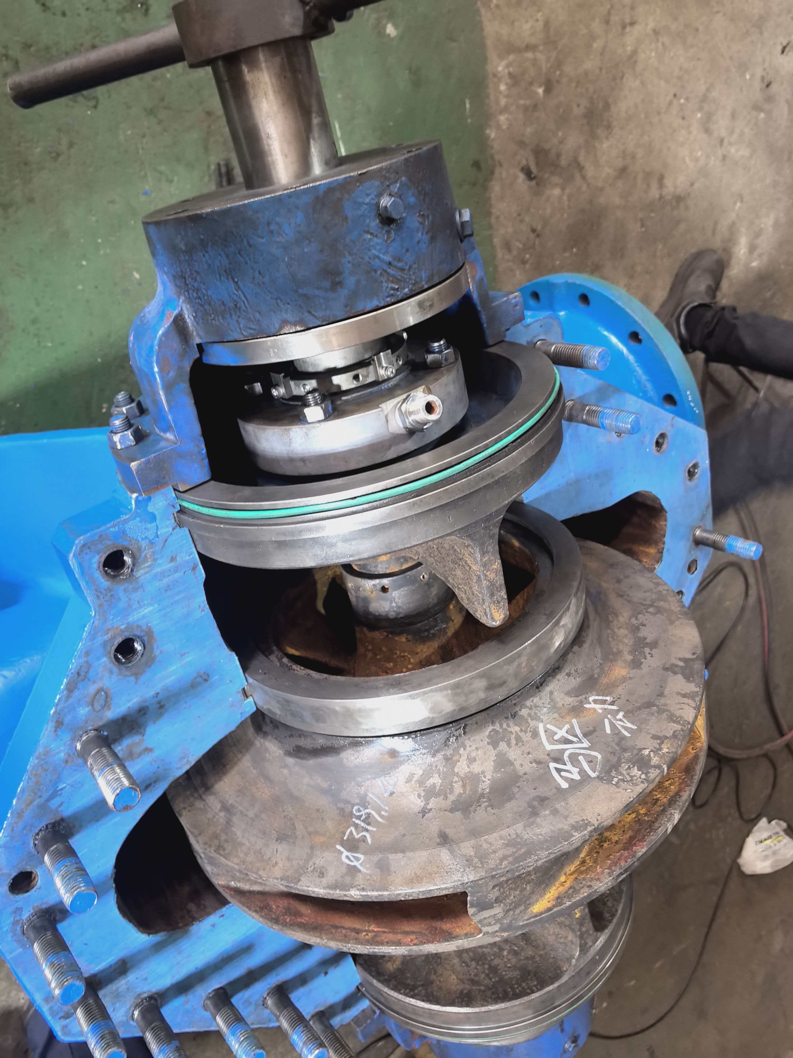
High-pressure vacuum residue pumps operate under demanding conditions that require robust sealing solutions to prevent product loss and environmental contamination. Leakage in these critical applications represents a significant operational challenge, affecting both profitability and regulatory compliance. API 682 Plan 53B has emerged as a preferred configuration for managing leakage risks in vacuum residue service, offering enhanced protection compared to earlier seal plan standards.
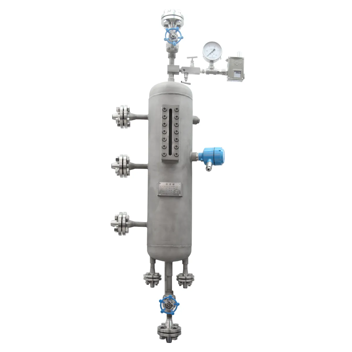
Understanding the distinction between API 682 Plan 53B and API 682 Plan 53A is essential for engineers selecting mechanical seal systems. Both configurations provide specific leakage control mechanisms, but API 682 Plan 53B delivers superior performance in high-pressure vacuum residue applications. This article explores the technical differences, operational benefits, and selection criteria that make each plan suitable for distinct process requirements.
Understanding API 682 Seal Plans and Leakage Control
Fundamentals of Mechanical Seal Configuration
Mechanical seals prevent fluid leakage at pump shaft interfaces where rotating and stationary components meet. API 682 standardizes seal plan configurations globally, ensuring consistency across refineries, petrochemical facilities, and processing plants. Each API 682 plan designation specifies the arrangement of restrictors, buffers, and thermal management systems that define how a seal responds to pressure differentials and temperature variations. API 682 Plan 53B represents one of the most comprehensive configurations available for challenging applications.
The pressure differential across a mechanical seal drives leakage potential. In vacuum residue service, where viscous, high-temperature fluids create extreme thermal stress, the seal must balance pressure loads while maintaining effective face contact. API 682 Plan 53B incorporates dual film stages that distribute pressure more evenly, reducing the mechanical stress concentrated on seal faces compared to simpler configurations like API 682 Plan 53A. This architecture directly addresses the leakage mechanisms inherent to high-pressure vacuum residue pumps.
Role of Barrier Fluids in Leakage Prevention
Both API 682 Plan 53B and API 682 Plan 53A employ barrier fluid systems to reduce direct contact between process fluid and seal faces. The barrier fluid creates a controlled pressure zone that isolates the seal from the most aggressive product conditions. In API 682 Plan 53B, the dual-stage design allows the barrier fluid to function more efficiently by reducing temperature rise and maintaining more stable pressure at the seal interface. This superior thermal and pressure stability translates into measurably lower leakage rates in vacuum residue service.
The barrier fluid quality and circulation rate directly impact leakage performance. API 682 Plan 53B systems require careful barrier fluid specification and monitoring, but the investment in proper fluid management yields significant leakage reduction. Without adequate barrier fluid circulation, even an API 682 Plan 53B configuration cannot achieve optimal performance, making system commissioning and maintenance critical factors in long-term reliability.
API 682 Plan 53B: Superior Design for Vacuum Residue Applications
Dual-Stage Architecture and Pressure Distribution
API 682 Plan 53B employs a dual-stage mechanical seal assembly that creates two distinct pressure reduction zones. The first stage reduces pressure from the pump discharge to an intermediate level, while the second stage further reduces pressure before reaching the bearing cavity. This staged approach fundamentally changes how the seal tolerates the extreme pressure differentials encountered in vacuum residue pumping. API 682 Plan 53B distributes mechanical loads across more seal surface area, reducing wear rates and extending seal life while simultaneously lowering leakage.
The thermal management inherent in API 682 Plan 53B designs proves particularly valuable in vacuum residue service. As barrier fluid circulates through both stages, it dissipates frictional heat more effectively than single-stage configurations. Temperature stability at the seal faces becomes more maintainable, which preserves rubber component elasticity and maintains precise gap spacing between rotating and stationary seal faces. Consistent thermal conditions directly support the pressure film that prevents leakage across the mechanical interface.
Leakage Rate Performance in High-Pressure Service
Field data from refineries operating API 682 Plan 53B in vacuum residue applications demonstrates leakage rates typically 40-60 percent lower than single-stage seal plans. The quantifiable reduction in product loss justifies the investment in API 682 Plan 53B systems, particularly in high-capacity pump installations where even modest leakage rates accumulate into significant annual product losses. Documentation of actual leakage performance requires proper measurement infrastructure and maintenance discipline, but the long-term economic case for API 682 Plan 53B in vacuum residue service remains compelling.
Leakage patterns in API 682 Plan 53B installations typically remain stable throughout normal seal life, avoiding the escalating leakage trends sometimes observed with single-stage designs. As seal faces experience wear, API 682 Plan 53B plans accommodate increased gap spacing better than API 682 Plan 53A, maintaining acceptable leakage control longer into the seal life cycle. This extended stable performance window reduces emergency maintenance frequency and associated downtime costs.
API 682 Plan 53A: Application Scope and Leakage Characteristics
Single-Stage Design and Pressure Management
API 682 Plan 53A provides a simpler, single-stage configuration suitable for moderate pressure applications and less critical service conditions. The single-stage architecture concentrates pressure reduction across one seal face pair, which works adequately for many industrial applications but proves insufficient for high-pressure vacuum residue pumping. API 682 Plan 53A accepts higher leakage rates as an inherent trade-off for reduced system complexity and lower initial capital investment. In suitable applications, this trade-off remains acceptable; in vacuum residue service, leakage losses typically exceed acceptable operating limits.
The thermal profile of API 682 Plan 53A differs significantly from API 682 Plan 53B due to concentrated heat generation at a single seal interface. In high-pressure vacuum residue applications, this thermal concentration can approach or exceed barrier fluid cooling capacity, creating temperature excursions that accelerate seal face erosion and widen face gaps. As gaps widen, leakage increases exponentially, often triggering premature seal replacement before statistical design life expectations.
Leakage Rate Characteristics and Operational Limitations
API 682 Plan 53A generates higher baseline leakage rates due to larger pressure differentials across the seal faces and reduced cooling efficiency. In vacuum residue service specifically, the combination of elevated temperature, high viscosity, and pressure differential means API 682 Plan 53A configurations frequently leak at rates exceeding facility environmental permits or process economics. Operators cannot reliably control leakage in API 682 Plan 53A installations under maximum design vacuum residue conditions, making this configuration unsuitable for modern refineries prioritizing environmental performance.
Leakage progression in API 682 Plan 53A systems accelerates over time in vacuum residue service. Early-life leakage may appear manageable, but material wear and thermal cycling progressively increase leakage until replacement becomes necessary. The rate of increase depends heavily on operational discipline and maintenance quality, but even optimal installation and operation cannot overcome the fundamental design limitations of API 682 Plan 53A in high-pressure vacuum residue applications.
Comparative Analysis: When to Specify Each Configuration
Selection Criteria for API 682 Plan 53B
Specify API 682 Plan 53B for vacuum residue pumps operating at discharge pressures exceeding 200 psi or handling viscous fluids above 500 cSt at operating temperature. API 682 Plan 53B becomes mandatory when environmental regulations limit allowable leakage or when process economics depend on minimizing product loss. Facilities processing high-value residue streams or operating under strict environmental compliance frameworks benefit most from API 682 Plan 53B's superior leakage control, justifying the higher system cost through reduced product loss and compliance confidence.
API 682 Plan 53B proves essential for new pump installations in vacuum residue service, retrofit upgrades to existing problem pumps, and any application where leakage has generated operational or regulatory concerns. The technology also provides insurance against future regulatory tightening, as API 682 Plan 53B inherently maintains lower emissions that accommodate more stringent standards.
Selection Criteria for API 682 Plan 53A
API 682 Plan 53A suits lower-pressure applications, less viscous fluids, and processes where moderate leakage remains acceptable. Reserve API 682 Plan 53A for retrofit situations involving severe budget constraints or temporary service applications where equipment life expectations remain limited. In normal refinery vacuum residue service, API 682 Plan 53A should not be specified as a primary design choice, as the leakage penalties typically outweigh capital savings within one to two operating years.
FAQ
What specific leakage rate difference should I expect between API 682 Plan 53B and API 682 Plan 53A in vacuum residue service?
API 682 Plan 53B typically achieves leakage rates 40-60 percent lower than API 682 Plan 53A under identical vacuum residue operating conditions. Actual leakage depends on specific pressure differentials, temperature profiles, fluid properties, and maintenance discipline. API 682 Plan 53B can often achieve leakage rates below 5 gallons per year in high-pressure vacuum residue service, while API 682 Plan 53A frequently exceeds 15-25 gallons annually under comparable conditions.
Can API 682 Plan 53A be upgraded to perform like API 682 Plan 53B for existing vacuum residue pumps?
No; API 682 Plan 53A and API 682 Plan 53B represent fundamentally different mechanical designs that cannot be retrofitted into equivalent performance levels. Upgrading existing vacuum residue pumps requires mechanical seal replacement with genuine API 682 Plan 53B assemblies, including dual-stage cartridges, appropriate barrier fluid systems, and supporting instrumentation. This retrofit investment typically costs 60-80 percent of a complete pump replacement but eliminates chronic leakage issues and extends pump asset value.
How does barrier fluid temperature impact leakage performance in API 682 Plan 53B systems?
Barrier fluid temperature directly controls leakage rates in API 682 Plan 53B configurations; each 10-degree Celsius increase in barrier temperature can increase leakage by 15-20 percent due to reduced viscosity and thermal expansion effects. Maintaining barrier fluid temperature within specified ranges (typically 40-60 degrees Celsius) requires adequate cooler capacity and circulation rate. API 682 Plan 53B's dual-stage design accommodates temperature variations better than single-stage configurations, but thermal management remains critical for optimal leakage control in vacuum residue service.
Table of Contents
- Understanding API 682 Seal Plans and Leakage Control
- API 682 Plan 53B: Superior Design for Vacuum Residue Applications
- API 682 Plan 53A: Application Scope and Leakage Characteristics
- Comparative Analysis: When to Specify Each Configuration
-
FAQ
- What specific leakage rate difference should I expect between API 682 Plan 53B and API 682 Plan 53A in vacuum residue service?
- Can API 682 Plan 53A be upgraded to perform like API 682 Plan 53B for existing vacuum residue pumps?
- How does barrier fluid temperature impact leakage performance in API 682 Plan 53B systems?