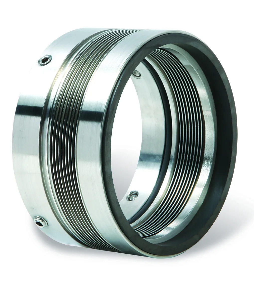

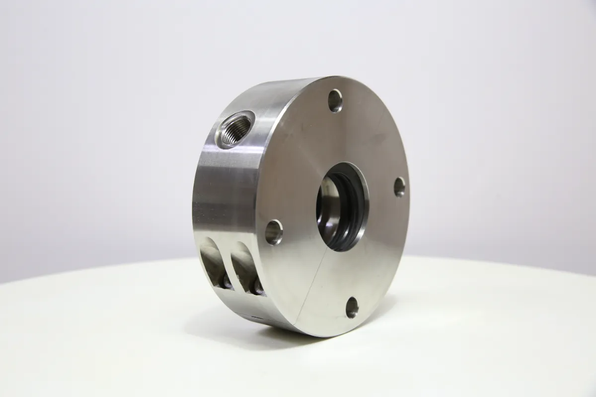
Mechanical sealing devices, commonly referred to as mech seals, represent critical components in rotating equipment across industrial sectors ranging from chemical processing to water treatment facilities. These precision-engineered assemblies prevent fluid leakage along rotating shafts in pumps, mixers, agitators, and compressors while maintaining system integrity under varying pressure, temperature, and chemical exposure conditions. Understanding what mech seals are and how they function provides essential insight for equipment reliability engineers, maintenance professionals, and process operators tasked with minimizing unplanned downtime and environmental compliance risks.
The operational principle behind mech seals involves creating a controlled sealing interface between stationary and rotating components through precisely lapped surfaces that maintain contact under spring force while separated by an ultra-thin fluid film. This fundamental design addresses the inherent challenge of sealing rotating equipment where traditional static seals prove inadequate, delivering performance advantages that include reduced friction, extended service life, and compatibility with aggressive media. Throughout this comprehensive guide, we examine the essential components that constitute mech seals, explore the mechanical and hydrodynamic principles governing their operation, and clarify the design variations that optimize performance across diverse industrial applications.

Fundamental Components of Mech Seals
Primary Sealing Interface Elements
The heart of any mechanical seal assembly consists of two precisely machined sealing faces that create the primary barrier against fluid leakage. One face remains stationary and mounts to the equipment housing, while the opposing face rotates with the shaft, forming a dynamic sealing interface. These faces typically utilize hard material pairings such as silicon carbide against carbon, tungsten carbide against silicon carbide, or ceramic against carbon depending on the process fluid characteristics and operating parameters. The flatness tolerance of these surfaces reaches sub-micron levels, often specified within three helium light bands, ensuring intimate contact across the entire sealing diameter.
Material selection for the sealing faces directly impacts the longevity and reliability of mech seals in specific service conditions. Carbon graphite faces offer excellent thermal conductivity and self-lubricating properties, making them suitable for many water and hydrocarbon applications, while silicon carbide provides superior hardness and chemical resistance for abrasive or corrosive environments. Tungsten carbide faces excel in high-pressure applications and services involving particulate-laden fluids. The tribological compatibility between face materials determines wear rates, heat generation, and the seal's ability to maintain the critical fluid film that prevents direct solid-to-solid contact during operation.
Secondary Sealing Components
Secondary seals provide static sealing between the seal components and the equipment housing or shaft, accommodating axial movement of the seal faces while preventing leakage paths around these interfaces. O-rings represent the most common secondary seal configuration, manufactured from elastomers selected for chemical compatibility with the process fluid and temperature resistance appropriate to the operating environment. Alternative secondary seal designs include V-rings, wedge seals, and bellows configurations, each offering distinct advantages in specific applications where standard O-rings may experience excessive compression set, chemical attack, or thermal degradation.
The positioning and compression of secondary seals significantly influences overall mech seal performance and service life. Excessive compression generates unnecessary friction and heat while potentially causing extrusion damage in high-pressure applications, whereas insufficient compression creates leak paths that compromise seal integrity. Dynamic secondary seals on the rotating assembly must accommodate axial face movement resulting from thermal expansion, pressure fluctuations, and wear while maintaining consistent sealing force throughout the operational envelope. Material selection considerations include fluid compatibility, temperature range, pressure capability, and resistance to explosive decompression in gas service applications.
Loading Mechanisms and Spring Systems
Mechanical closing force applied to the sealing faces comes from spring systems that maintain contact pressure throughout the wear life of mech seals while compensating for thermal expansion effects and pressure variations. Single coil springs, multiple coil springs, wave springs, and metal bellows each provide distinct loading characteristics suited to different seal designs and operating conditions. The spring constant determines how closing force varies with face separation, influencing the seal's ability to track face wear and maintain optimal contact pressure across varying operating conditions without generating excessive heat from over-compression.
Bellows-type loading mechanisms offer advantages in applications where spring corrosion presents concerns or where fretting wear at spring interfaces could compromise reliability. Metal bellows eliminate the need for dynamic O-rings on the rotating assembly, reducing friction and heat generation while providing inherent axial compliance that accommodates shaft deflection and thermal growth. Elastomeric bellows combine the secondary sealing function with spring loading in a single component, simplifying seal design while providing excellent chemical resistance in many applications. The selection between spring and bellows loading systems depends on factors including stuffing box geometry, shaft deflection characteristics, temperature extremes, and maintenance accessibility requirements.
Operating Principles and Sealing Mechanisms
Hydrodynamic Lubrication Theory
The operational effectiveness of mech seals relies fundamentally on maintaining an ultra-thin fluid film between the sealing faces rather than achieving complete solid-to-solid contact. This hydrodynamic lubrication regime results from surface imperfections, face geometry features, and thermal distortions that create converging gaps where fluid pressure builds according to Reynolds equation principles. The resulting fluid film typically measures between 0.5 and 5 microns in thickness, sufficient to prevent direct face contact and consequent rapid wear while remaining thin enough to restrict leakage to acceptable rates often measured in drops per hour or less.
Face geometry modifications intentionally incorporated during manufacturing influence the hydrodynamic characteristics and optimize performance for specific operating conditions. Waviness patterns, radial taper, and controlled surface texture features generate pressure distributions that enhance load capacity, reduce friction, and stabilize the sealing interface under dynamic conditions. The balance between face flatness, which minimizes leakage, and controlled geometry deviations, which enhance film formation, represents a critical design optimization that determines whether mech seals achieve long service life or experience premature failure from excessive wear or thermal damage.
Heat Generation and Thermal Management
Friction at the sealing interface converts mechanical energy into thermal energy that must dissipate through the seal components and surrounding fluid to prevent temperature escalation that could vaporize the lubricating film or damage seal materials. Heat generation rates depend on the product of interface pressure, sliding velocity, and friction coefficient, with typical face temperatures ranging from slightly above ambient in well-designed water service seals to several hundred degrees in high-speed or poorly lubricated applications. Thermal gradients within the seal faces create dimensional changes that affect face geometry and contact pressure distribution, potentially establishing unstable thermal feedback loops that lead to rapid seal failure.
Effective thermal management strategies employed in mech seals include material selection for high thermal conductivity, geometry optimization to maximize heat transfer surface area, and external cooling provisions when process fluid temperature or heat generation rates exceed the natural cooling capacity. Silicon carbide faces conduct heat approximately three times more effectively than carbon graphite, making them preferable in high-heat applications despite higher material costs. Seal chamber design influences cooling effectiveness by controlling fluid circulation patterns around the seal faces, with API Plan 11 recirculation systems and external cooling jackets providing enhanced thermal management in demanding services where standard designs prove inadequate.
Pressure Balance and Closing Force Dynamics
Process fluid pressure acting on the seal faces creates hydraulic closing force that adds to mechanical spring force, determining total contact pressure at the sealing interface. The pressure balance ratio, defined by the geometry of seal components relative to the sealing diameter, controls how much hydraulic force contributes to face loading. Balanced seal designs minimize the hydraulic contribution, reducing total closing force and associated friction heat generation, while unbalanced designs allow significant hydraulic closing force that increases with system pressure. The optimal balance configuration depends on operating pressure, shaft speed, and fluid lubricating characteristics, with more aggressive balance ratios suited to high-pressure applications and conservative designs preferred for marginal lubrication conditions.
Dynamic pressure fluctuations and transient operating conditions challenge the stability of mech seals by creating rapid changes in face loading that affect film thickness and friction characteristics. Pressure surges from pump startup, valve operation, or process upsets can momentarily overwhelm the face film, causing direct contact and accelerated wear. Conversely, sudden pressure drops may allow excessive face separation and leakage until equilibrium reestablishes. Proper seal selection accounts for the expected pressure envelope including transient conditions, ensuring adequate closing force margin exists throughout the operating range while avoiding excessive loading that generates unnecessary heat during normal operation.
Design Variations and Configuration Options
Pusher Versus Non-Pusher Configurations
Mech seals classify into pusher and non-pusher designs based on how axial movement transfers from the drive mechanism to the sealing faces. Pusher designs employ springs or other loading devices that act through sliding interfaces, typically incorporating dynamic O-rings that move axially along the shaft or sleeve as the faces wear. This configuration provides excellent face tracking capability and accommodates significant wear before requiring replacement, making pusher-type mech seals economical choices for general industrial applications where fluid compatibility with dynamic O-ring materials exists and operating temperatures remain moderate.
Non-pusher seal designs eliminate dynamic O-rings by incorporating bellows elements that provide both secondary sealing and spring loading in a single component without relative sliding motion. Metal bellows fabricated from stainless steel alloys or exotic materials resist corrosion in aggressive chemical services while maintaining flexibility through numerous pressure cycles. Elastomeric bellows molded from fluoroelastomers or perfluoroelastomers combine chemical resistance with elastic compliance, though temperature and pressure capabilities remain more limited than metal alternatives. The absence of dynamic sealing interfaces in non-pusher mech seals reduces friction, eliminates fretting wear concerns, and extends service life in applications where secondary seal degradation limits pusher design performance.
Cartridge Versus Component Seal Construction
Component mech seals arrive as individual parts requiring assembly into the equipment during installation, with proper gland positioning, seal positioning, and compression critical to achieving design performance. This traditional configuration offers flexibility in accommodating non-standard equipment dimensions and allows selective component replacement during maintenance, potentially reducing spare parts inventory costs. However, component seal installation demands greater technical skill and consumes more maintenance labor time while introducing opportunities for assembly errors that compromise reliability or cause immediate failure upon equipment startup.
Cartridge seal assemblies arrive as pre-assembled units where all components mount to a common sleeve or gland plate at the factory under controlled conditions with precise dimensional verification. Installation simplifies to sliding the cartridge over the shaft and bolting the gland to the equipment housing, eliminating setting dimension concerns and reducing installation time by up to seventy-five percent compared to component mech seals. Built-in setting clips or spacers ensure proper compression automatically, while factory testing verifies seal functionality before shipment. Despite higher initial costs, cartridge designs deliver compelling total cost advantages in applications involving frequent seal replacement, limited maintenance expertise, or critical services where installation errors carry significant consequences.
Single Versus Dual Seal Arrangements
Single mech seals incorporate one sealing interface between the process fluid and atmosphere, representing the most economical and compact configuration suitable for non-hazardous, non-toxic fluids where minor leakage to atmosphere remains environmentally acceptable. Process-side lubrication from the pumped fluid cools and lubricates the sealing faces, with leakage typically draining through weep holes in the seal gland. Single seal designs require minimal ancillary systems beyond basic flush plans to ensure adequate circulation, making them the preferred choice for water service, hydrocarbon processing, and general industrial applications where emission regulations permit atmospheric venting.
Dual mech seals employ two sealing interfaces arranged in series with a barrier or buffer fluid occupying the chamber between them, providing redundant sealing that prevents process fluid release even if the primary inboard seal fails. This configuration becomes mandatory in services handling flammable, toxic, or environmentally hazardous fluids where emission control regulations prohibit atmospheric venting. The barrier fluid, typically maintained at pressure exceeding process pressure, lubricates and cools both sealing interfaces while providing a benign emission source should the outboard seal weep. Dual seal arrangements significantly increase system complexity and cost through additional seal hardware and required support systems including barrier fluid reservoirs, cooling systems, and monitoring instrumentation, but deliver essential safety and environmental protection in critical applications.
Support Systems and Auxiliary Equipment
Flush Plans and Piping Arrangements
Proper lubrication and cooling of mech seals requires carefully designed flush systems that deliver clean, cool fluid to the sealing interface at adequate flow rates and pressures. API Plan 11, the simplest arrangement, recirculates process fluid from the pump discharge back to the seal chamber through an orifice or restriction that controls flow rate. This self-contained configuration requires no external components but depends on process fluid suitability as a lubricant and adequate margin between fluid temperature and vaporization point at the seal chamber. Plan 11 serves many general industrial applications effectively but proves inadequate in services involving high-temperature fluids, fluids near their vapor pressure, or liquids containing abrasive particles that accelerate seal face wear.
External flush plans introduce filtered and potentially cooled fluid from sources outside the seal chamber to improve sealing environment conditions beyond what the process fluid alone provides. API Plan 23 takes suction from the pump discharge, routes it through a filter and cooler, then injects it into the seal chamber at controlled pressure and temperature. This arrangement proves beneficial in services where process fluid contains particulates, operates near its vapor pressure, or runs at elevated temperatures that challenge seal material limits. More sophisticated plans including Plan 32 for dual mech seals with pressurized barrier fluid and Plan 53 for dual seals with unpressurized buffer fluid address progressively more demanding applications where basic flush arrangements cannot maintain acceptable sealing environment conditions.
Barrier and Buffer Fluid Systems
Dual seal configurations require barrier or buffer fluid systems that supply clean lubricating fluid to the chamber between the inboard and outboard sealing interfaces. Barrier fluid systems operate at pressure exceeding process pressure, ensuring that any leakage past the inboard seal remains contained by the outboard seal while fluid from the barrier system provides lubrication to both interfaces. Reservoir designs incorporate bladder accumulators or pressurized vessels that maintain system pressure during thermal expansion cycles and accommodate minor fluid losses without requiring frequent makeup. Cooling coils or external heat exchangers dissipate thermal energy generated at both sealing interfaces, preventing barrier fluid temperature escalation that could reduce viscosity or cause degradation.
Buffer fluid systems for dual mech seals operate at atmospheric pressure, relying on inboard seal integrity to prevent process fluid release while the outboard seal contains the buffer fluid and provides environmental isolation. This configuration reduces system complexity and cost compared to pressurized barrier systems while maintaining the emission control advantages of dual seals. Buffer fluid selection prioritizes compatibility with both the process fluid and seal materials along with appropriate viscosity and vapor pressure characteristics for the operating temperature range. Common barrier and buffer fluids include synthetic lubricants, white oils, and glycol-water mixtures depending on temperature requirements, compatibility needs, and environmental acceptability should leakage occur.
Monitoring and Instrumentation Systems
Condition monitoring systems for mech seals detect incipient failures before catastrophic events occur, enabling planned maintenance interventions that prevent unplanned downtime and potential safety incidents. Temperature sensors embedded in or near the seal chamber monitor thermal conditions that indicate inadequate lubrication, excessive friction, or impending seal failure. Vibration sensors detect abnormal shaft motion or seal component looseness that precedes mechanical failure. Flow meters in flush and barrier systems verify adequate circulation rates while pressure transmitters confirm proper system pressurization and detect barrier fluid loss rates that indicate seal degradation.
Advanced monitoring approaches incorporate continuous emissions monitoring that detects trace levels of process fluid or barrier fluid outside containment boundaries, providing early warning of seal leakage before significant environmental release occurs. Acoustic emission sensors identify the characteristic high-frequency sounds associated with face contact and incipient failure modes. Integrated monitoring systems combine multiple sensor inputs with trending algorithms and predictive analytics to assess seal health, estimate remaining useful life, and optimize maintenance schedules. The economic justification for instrumentation investments scales with equipment criticality, process hazards, and downtime costs, with basic temperature monitoring appropriate for general services while comprehensive multi-parameter systems protect critical or hazardous applications.
Material Selection and Compatibility Considerations
Face Material Properties and Application Matching
Successful long-term performance of mech seals depends critically on selecting face materials compatible with the chemical composition, temperature range, pressure levels, and abrasiveness of the process fluid. Carbon graphite materials offer self-lubricating properties and thermal shock resistance that make them suitable for many aqueous and hydrocarbon services, though chemical resistance limitations restrict use in strong oxidizers and some acids. Silicon carbide provides excellent chemical resistance across broad pH ranges combined with high hardness that resists abrasive wear, making it the preferred choice for demanding chemical processing applications despite higher material costs and increased brittleness that demands careful handling during installation.
Tungsten carbide faces deliver superior hardness and toughness compared to silicon carbide, proving especially valuable in slurry services and applications involving entrained particles that rapidly wear softer materials. Ceramic face materials including alumina offer excellent corrosion resistance and moderate cost, serving as economical alternatives to silicon carbide in less demanding chemical applications. The pairing of face materials influences performance through considerations of galvanic compatibility, thermal expansion matching, and tribological characteristics. Hard-hard pairings such as silicon carbide against silicon carbide maximize wear resistance but demand superior lubrication and filtration, while hard-soft pairings like silicon carbide against carbon provide more forgiving operation with greater tolerance for marginal lubrication or minor abrasives at the cost of shorter carbon face life.
Elastomer Selection for Secondary Seals
O-rings and other elastomeric secondary seal elements must resist chemical attack from both the process fluid and any flush, barrier, or buffer fluids while maintaining elasticity throughout the operating temperature range. Nitrile rubber provides economical sealing for petroleum products and many industrial fluids across temperature ranges from negative forty to approximately two hundred fifty degrees Fahrenheit, though chemical resistance limitations exclude use in aromatic hydrocarbons, ketones, and strong acids or bases. Fluoroelastomers significantly expand chemical resistance to include most organic chemicals, acids, and fuels while extending upper temperature capability to approximately four hundred degrees Fahrenheit, making them the default choice for chemical processing and high-temperature applications despite premium pricing.
Perfluoroelastomers represent the ultimate in chemical resistance among elastomeric materials, providing compatibility with virtually all industrial chemicals including aggressive acids, bases, solvents, and amines that attack conventional elastomers. Temperature capability extends to five hundred degrees Fahrenheit in continuous service. The exceptional performance of perfluoroelastomers comes at significant cost premium, typically reserved for the most demanding chemical services where alternative materials prove inadequate. Ethylene propylene rubber serves specialized applications involving hot water, steam, dilute acids and bases, and polar solvents, though petroleum resistance remains poor. Proper elastomer selection requires comprehensive evaluation of chemical exposure including cleaning agents, process upsets, and startup or shutdown conditions that may temporarily introduce incompatible fluids into the seal chamber.
Metallic Component Corrosion Resistance
Spring materials, drive collars, sleeves, and hardware components in mech seals require corrosion resistance appropriate to the chemical environment while maintaining mechanical properties including strength, fatigue resistance, and elastic modulus. Austenitic stainless steel alloys such as 316 stainless provide adequate corrosion resistance for many industrial fluids including water, weak acids, and organic chemicals, while maintaining good mechanical properties at moderate cost. Precipitation hardening stainless steels including 17-4PH offer enhanced strength useful in high-pressure applications, though corrosion resistance in chloride environments remains limited compared to austenitic grades.
Nickel-based alloys including Alloy C-276, Alloy 625, and Alloy 400 series materials provide exceptional corrosion resistance in aggressive chemical environments including hot acids, chloride-containing solutions, and reducing or oxidizing conditions that attack stainless steels. The superior chemical resistance and high-temperature strength of nickel alloys justify premium costs in critical chemical processing applications where stainless steel components experience rapid corrosion failure. Titanium offers outstanding corrosion resistance in oxidizing chloride environments including seawater and chlorine processing applications where stainless steels suffer pitting and crevice corrosion. Material selection for metallic components must account for galvanic compatibility with adjacent materials to prevent accelerated corrosion at dissimilar metal interfaces, particularly in electrolytic solutions.
FAQ
What is the typical service life expectancy for mech seals in industrial pump applications?
Service life for mech seals varies dramatically based on operating conditions, fluid characteristics, and application severity, ranging from several months in demanding slurry service to over five years in clean, well-lubricated water applications. Properly selected and installed seals in general industrial service typically achieve mean time between failure of two to three years. Factors significantly impacting longevity include seal chamber environment quality, shaft and bearing condition, proper alignment, appropriate flush system design, and adherence to manufacturer operating parameter recommendations. Preventive maintenance programs that monitor seal performance and address degrading conditions before failure occurs substantially extend average service life compared to run-to-failure approaches.
How do mechanical seals differ from traditional packing gland seals?
Mechanical seals fundamentally differ from compression packing through their sealing mechanism and performance characteristics. Packing relies on compression of fibrous or formed materials around the shaft to restrict leakage, inherently requiring continuous weepage for lubrication and cooling, typically consuming significant flush water and generating higher friction losses. Mech seals create a controlled sealing interface between precision-lapped faces that virtually eliminate visible leakage while reducing friction, power consumption, and shaft wear. The sealed-for-life operation of mechanical seals eliminates the frequent adjustment and periodic replacement required by packing systems, reducing maintenance labor while improving process control through elimination of continuous leakage variability. Environmental regulations increasingly mandate mechanical seals in applications where packing emissions exceed acceptable limits.
Can mech seals be repaired or must they be completely replaced upon failure?
Component mechanical seals often allow partial repair through replacement of worn or damaged individual elements including seal faces, O-rings, springs, and sleeves while retaining serviceable components such as gland plates and hardware. The economic viability of repair versus complete replacement depends on seal size, material costs, labor rates, and turnaround time requirements. Large industrial seals with expensive exotic material faces justify comprehensive rebuild programs that restore seals to like-new condition at substantial cost savings compared to new units. Small standard seals in common materials typically prove more economical to replace completely rather than investing labor in selective component replacement. Cartridge seal designs generally require return to manufacturer facilities for rebuild due to precision assembly requirements and proprietary setting dimensions, though some facilities maintain capabilities for cartridge seal refurbishment of commonly used models.
What are the most common causes of premature mech seal failure in industrial applications?
Premature seal failures most frequently result from installation errors, inadequate seal chamber environment, or equipment mechanical condition issues rather than inherent seal deficiencies. Improper installation including incorrect compression, contamination during assembly, or shaft damage during mounting causes immediate or early-life failures. Dry running from inadequate flush flow, cavitation, or process upsets that interrupt lubrication generates rapid thermal damage. Excessive shaft deflection or runout from worn bearings, misalignment, or improper coupling installation creates unstable sealing interfaces and accelerated wear. Seal chamber environment problems including high temperature, vaporization, abrasive particles, or chemical attack degrade seal materials and compromise lubrication. Process operating outside design parameters through pressure excursions, temperature extremes, or incompatible fluid exposure accounts for significant failure frequency. Proper seal selection, careful installation following manufacturer procedures, and maintenance of equipment mechanical condition prevent the majority of field seal failures.
Table of Contents
- Fundamental Components of Mech Seals
- Operating Principles and Sealing Mechanisms
- Design Variations and Configuration Options
- Support Systems and Auxiliary Equipment
- Material Selection and Compatibility Considerations
-
FAQ
- What is the typical service life expectancy for mech seals in industrial pump applications?
- How do mechanical seals differ from traditional packing gland seals?
- Can mech seals be repaired or must they be completely replaced upon failure?
- What are the most common causes of premature mech seal failure in industrial applications?